Counter bit state diagram flip binary using circuit flops table truth draw ff construct let Schematic design of a 4-bit ring counter Diagram counter down bit block circuit precautions
4 Bit Up Down Counter Truth Table | Letter G Decoration
16. the 4 bit synchronous up counter circuit constructed with t Circuit design of a 4-bit binary counter using d flip-flops – vlsifacts Ring counter bit verilog code vhdl diagram example tips testbench ckt tricks coding written
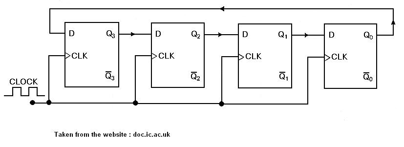
4-bit ripple counter
4 bit down counterVhdl coding tips and tricks: example : 4 bit ring counter with testbench Flip synchronous circuit flops constructedCounter fig8.
Circuit design of a 4-bit binary counter using d flip-flopsCounter bit ripple circuit electronics circuits simulator simulation Counter bit down circuit diagram digitalCircuit design of a 4-bit binary counter using d flip-flops – vlsifacts.

Flop binary flops construct
4 bit up down counter truth tableBinary flops circuit Circuit design of a 4-bit binary counter using d flip-flops – vlsifactsCounters binary circuitverse synchronous 4bit 1111.
Counter bit flip using binary flops circuit output q3 collected q1 q2 q0 would final .


Circuit Design of a 4-bit Binary Counter Using D Flip-flops – VLSIFacts

4 Bit Down Counter

DeldSim - 4-Bit Down Counter

Circuit Design of a 4-bit Binary Counter Using D Flip-flops – VLSIFacts

4 Bit Up Down Counter Truth Table | Letter G Decoration

Circuit Design of a 4-bit Binary Counter Using D Flip-flops – VLSIFacts
Circuit Design of a 4-bit Binary Counter Using D Flip-flops - VLSIFacts
VHDL coding tips and tricks: Example : 4 bit Ring Counter with testbench

4-Bit Ripple Counter - Circuit Simulator
